|
||||||||||
|
Model Code - top 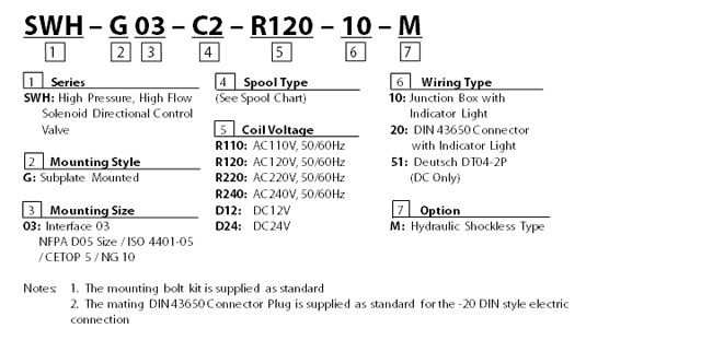 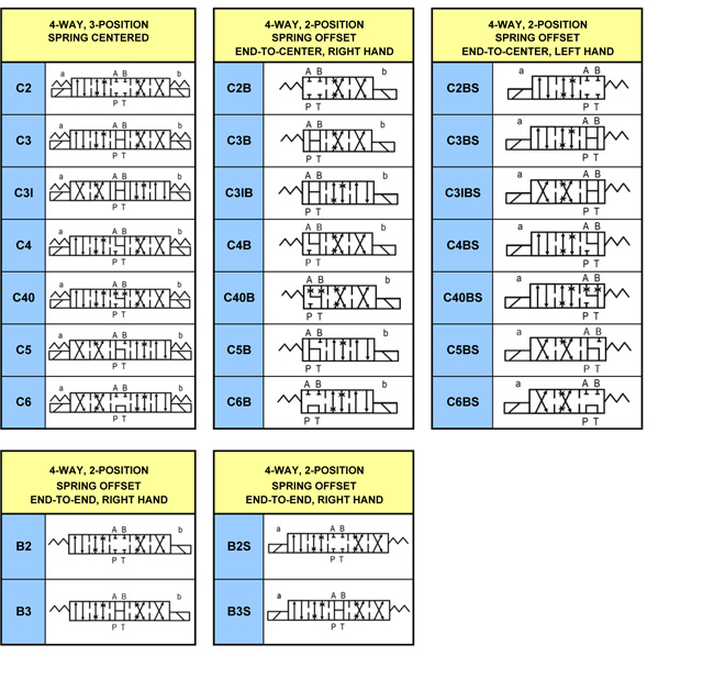 |
|||||||||||||||||||||||||||||||||||||||||||||||||||||||||||||||||||||||||||||||||||||||||||||||||||||||||||||||||||||||||||||||||||||||||||||||||||||||||||||||||||||||||||||||||||||||||||||||||||||||||||||||||||||||||||||||||||||||||||||||||||||||||||||||||||||||||||||||||||||||||||||||||
|
Specifications - top
Solenoid Ratings - top
TECHNICAL DATA: - top • Solenoid can be used within - 10% to + 10% of the rated voltage of the coil. • Withstand voltage 1500 v/sec. • Insulation resistance over 100MQ. ACCESSORIES: - top • Mounting bolt kits are supplied with valve socket head cap screws M6x35L 4 pcs (1/4"-20UNCx1-3/8" 4 pcs) for tightening torque 120-150 kgf-cm (104-130 lbs-in). • O-Ring AS568-014 5 pcs. PRESSURE DROP AND PERFORMANCE CURVES - top
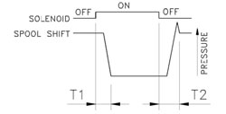
RESULTS OF MEASUREMENTS TEST SYSTEMS 1. Testing Valve 2. Pump 3. Pressure Sensor 4. Flow Sensor 5. Relief Valve 6. Throttle Valve TEST CONDITIONS Pressure: 138 BAR (2000PSI) Flow Rate: 30 LPM(8 GPM) Viscosity: 35 cSt(175 SSU) TEST CIRCUIT 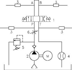
List of Spool Functions - top
|
|||||||||||||||||||||||||||||||||||||||||||||||||||||||||||||||||||||||||||||||||||||||||||||||||||||||||||||||||||||||||||||||||||||||||||||||||||||||||||||||||||||||||||||||||||||||||||||||||||||||||||||||||||||||||||||||||||||||||||||||||||||||||||||||||||||||||||||||||||||||||||||||||
|
Dimensions - top SWH - G03 - *** - **** - 10 - ** with DC/RF solenoids |
MOUNTING
SURFACE: ISO 4401-AB-03-4-A UNIT: mm( inch) |
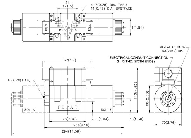
| MODEL | WEIGHT KGS (LBS) |
| SWH-G03-C**-D** | 5.5(12.1) |
| SWH-G03-C**-R*** | |
| SWH-G03-B**-D** | 4(9.68) |
| SWH-G03-B**-R*** |
![]()
|
Dimensions - top SWH - G03 - *** - **** - 20 - ** with DC,RF solenoids |
MOUNTING
SURFACE: ISO 4401-AB-03-4-A UNIT: mm( inch) |
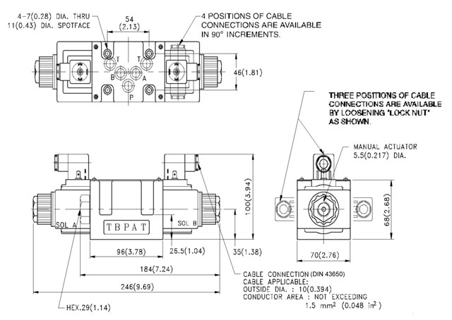
| MODEL | WEIGHT KGS (LBS) |
| SWH-G03-C**-D ** | 5.5(12.1) |
| SWH-G03-C**-R *** | |
| SWH-G03-B**-D ** | 4(9.68) |
| SWH-G03-B**-R *** |