SOLENOID OPERATED DIRECTIONAL VALVE

SWH-G02 SERIES  SHOCKLESS TYPE

FEATURES

• Armature operates in oil system. Impact is cushioned, noise is reduced, solenoid life is increased.
• Wet armature solenoid eliminates pushpin seal, therefore no seal wear, drop or leakage for longer valve life.
• Molded coils for maximum insulating properties, which is impervious to moisture and dirt.
• Plug-in solenoid, for ease of maintenance.
• All spools and bodies are interchangeable, simplifying maintenance.
• Indicating signal lights and bolt kits are standard.
• High pressure, high flow rating, provides low-pressure drop, with maximum performance.
• Specially designed, balanced spool allows proper shifting force, for maximum reliability and long life.
• A specially machined spool minimizes hydraulic shock caused by abrupt change in the flow condition at flow cut off.
• Hydraulic shock caused by abrupt change in the flow condition at flow cut off, is minimized by a specially machined


  Quick Links
Model Code
Specifications
Dimensions


Model Code -
top


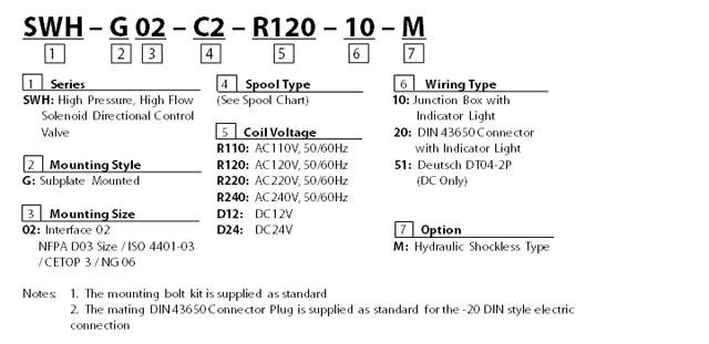
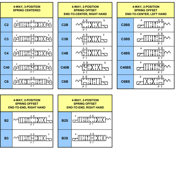
Specifications -
top


Maximum operating pressure 207 BAR (3000 PSI)
Rated flow capacity 40 LPM (10.5 GPM) MAX - Varies by spool type
Maximum tank line back pressure 138 BAR (2000 PSI)
Maximum frequencies of operation 120 CPM
Recommended filtration 25 MICRON
Hydraulic fluids Mineral Oil, Viscosity 10 - 400 cST
Temperature range 0° C to +55° C (32° F to +131° F)
 

Solenoid Ratings -
top
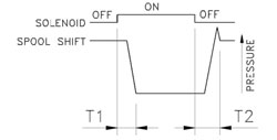
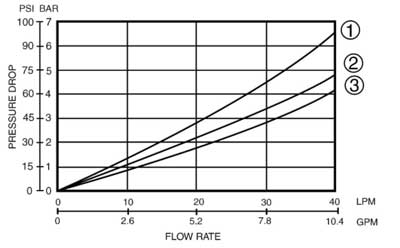

 
COIL TYPE VOLTAGE(V) CURRENT & POWER AT RATED VOLTAGE
SOURCE RATED  Hz RANGE (±10%) IN-RUSH CURRENT (A) HOLDING CURRENT (A) WATTAGE
R110 AC110V 50 99-121 0.30 0.30 26
  AC110V 60  
R220 AC220V 50 198-242 0.15 0.15
  AC220V 60  
D12 DC 12V 10.8-13.2 2.20 2.20
D24 DC 24V   21.6-26.4 1.10 1.10


TECHNICAL DATA: - top


Solenoid can be used within -10% to +10% of the rated voltage of the coil.
• Withstand voltage 1500 v/sec.
• Insulation resistance over 100mQ
• Conforms to rating IP65
• A momentary signal of approx 0.1 second is required for shifting action.


ACCESSORIES: - top


• Mounting bolt kits are supplied with valve socket head cap screws (#10-24UNCx1-3/4"L 4 pcs)
for tightening torque 50-70 kgf-cm (43.3-60.6 lb-in).
• O-Ring AS568-012 4 pcs.


PRESSURE DROP AND PERFORMANCE CURVES  - top
TEST SYSTEMS

1. Testing Valve
2. Pump
3. Pressure Sensor
4. Flow Sensor
5. Relief Valve
6. Throttle Valve

TEST CONDITIONS
Pressure: 69 BAR (1000PSI)
Flow Rate: 40 LPM(10.5GPM)
Viscosity: 35 cSt (175SSU)

TEST CIRCUIT

 
PERFORMANCE CURVES


CONTRAST CHART BETWEEN FACTORS AND VISCOSITIES
VISCOSITY cSt 15 20 30 40 50 60 70 80 90 100
SSU 77 98 141 186 232 278 324 371 417 464
FACTOR (G) 0.81 0.87 0.96 1.03 1.09 1.14 1.19 1.23 1.27 1.30

The pressure drop (AP') can be obtained from the formula
AP'=AP (G'/0.85) for other specific gravity (G').
SPOOL PRESSURE DROP CURVE  
TYPE P — A B — T P — B A — T
C2 2 2 2 2
C4 2 3 2 3
B3 1 1 2 2


TEST SYSTEMS - top

1. Testing Valve
2. Pump
3. Pressure Sensor
4. Flow Sensor
5. Relief Valve
6. Throttle Valve

TEST CONDITIONS
Pressure: 138 BAR (2000PSI)
Flow Rate: 30 LPM(8 GPM)
Viscosity: 35 cSt(175 SSU)


TEST CIRCUIT


MODEL CHANGE OVER TIME (SEC)
  T1  T2
SWH-G02-RF-M SERIES 0.10-0.15  0.10-0.15
SWH-G02-DC-M SERIES 0.10-0.15  0.10-0.15


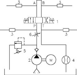
LIST OF SPOOL FUNCTIONS - top


THE MAXIMUM FLOW RATE LPM(GPM) UNDER DIFFERENT PRESSURE BAR (PSI)
SPOOL TYPE NORMAL POSITION 50 BAR (735 PSI) 100 BAR (1470 PSI) 140 BAR (2000 PSI) 210 BAR (3000 PSI) 50 BAR (735 PSI) 100 BAR (1470 PSI) 140 BAR (2000 PSI) 210 BAR (3000 PSI) 50 BAR (735 PSI) 100 BAR (1470 PSI) 140 BAR (2000 PSI) 210 BAR (3000 PSI)
C2 40 (10.7) 40 (10.7) 40 (10.7) 40 (10.7) 30 (8.0) 22 (5.9) 16 (4.3) 10 (2.7) 30 (8) 22 (5.9) 16 (4.3) 10 (2.7)
C4 40 (10.7) 40 (10.7) 40 (10.7) 40 (10.7) 30 (8.0) 22 (5.9) 16 (4.3) 10 (2.7) 30 (8) 22 (5.9) 16 (4.3) 10 (2.7)
B3 40 (10.7) 40 (10.7) 40 (10.7) 40 (10.7) 40 (10.7) 40 (10.7) 40 (10.7) 40 (10.7) 40 (10.7) 40 (10.7) 40 (10.7) 40 (10.7)


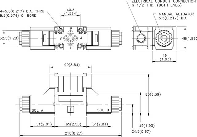
Dimensions -
top


SWH - G02 - C ** - **** - 10 - ** - M
with AC/DC/RF solenoids                         

MOUNTING SURFACE: ISO 4401-AB-03-4-A
UNIT: mm( inch) WEIGHT: 2.0 kgs (4.4 lbs)


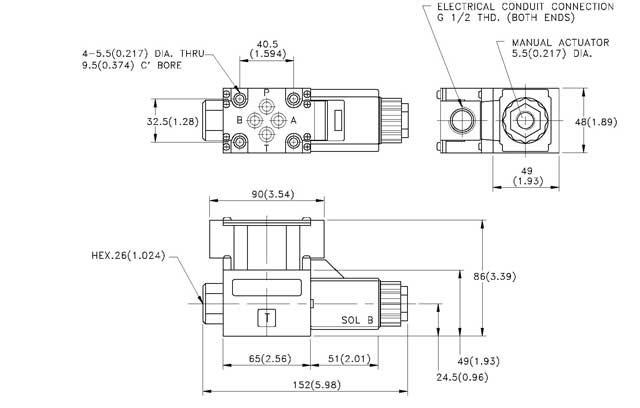
Dimensions -
top


SWH - G02 - B ** - **** - 10 - ** - M
with AC/DC/RF solenoids                         

MOUNTING SURFACE: ISO 4401-AB-03-4-A
UNIT: mm( inch) WEIGHT: 2.0 kgs (4.4 lbs)
 

Model and Weight- top


Model  Weight KGS(LBS) 
SWH-G02-B- A***-20-** - M 1.5(3.3)
SWH-G02-C - D/R ***20-** - M 2.0(4.4)
SWH-G02-B - D/R ***-20- ** - M 1.6(3.52)
SWH-G02-D- A ***-20- ** - M 1.9(4.18)
SWH-G02-D - D/R *** -20-** - M 1.9(4.18)